| Naval Construction and Propulsion | ||||||||||||||||||||||||||||||||||||||||||||||||||||||||||||||||||||||||||||||||||||||||||||||||
|
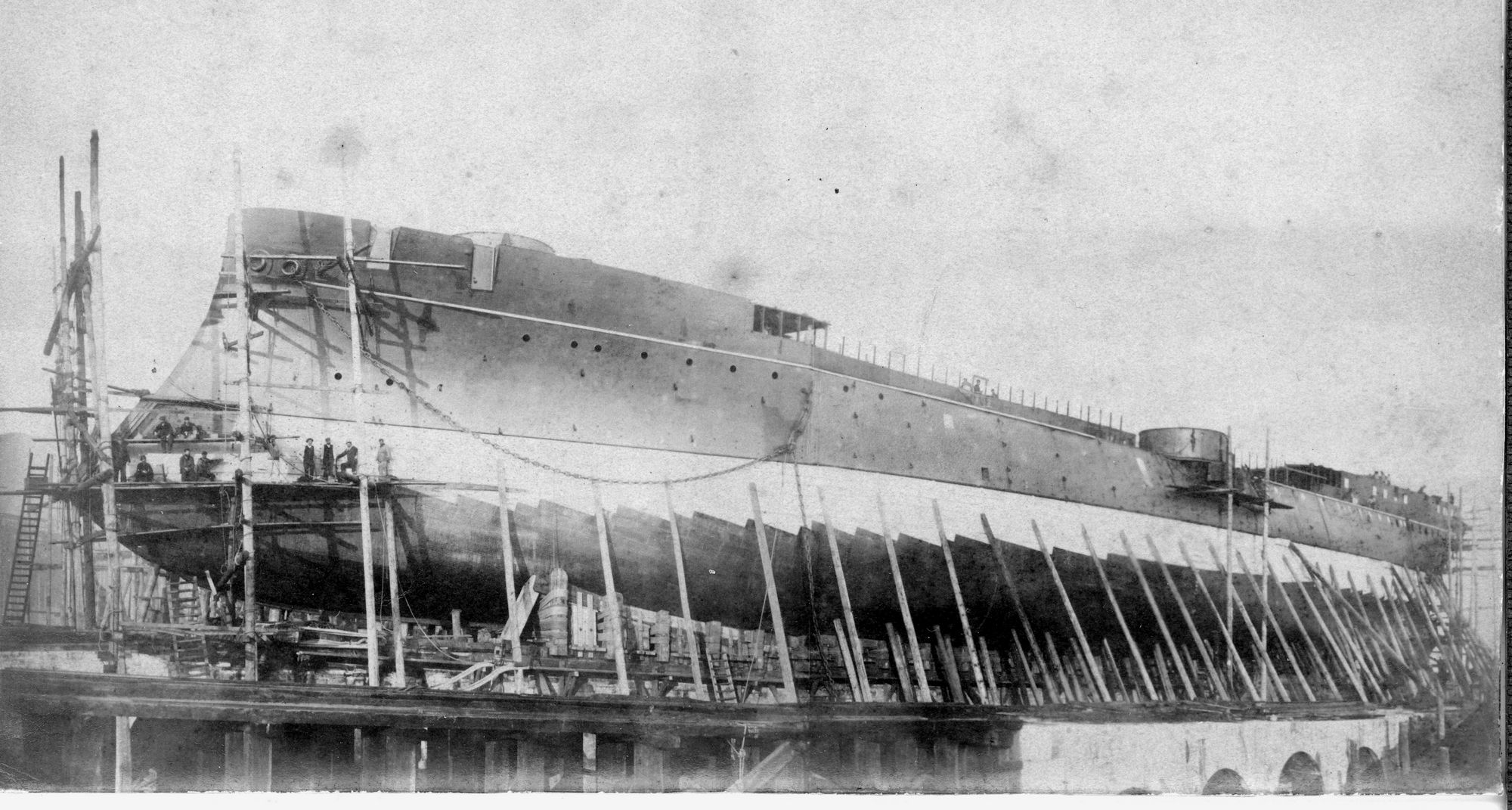
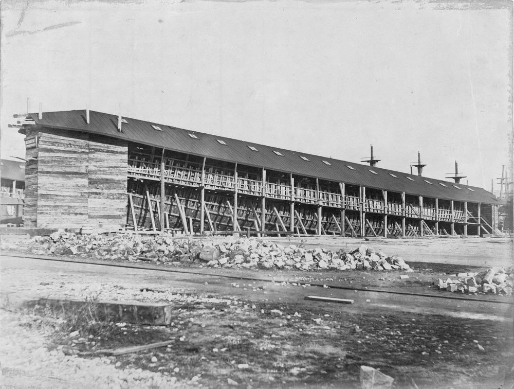
Catalogue number 136012 Captain Prat, a Chilean cruiser The construction of the ship (laid down 1889 and launched 1890) is well-advanced, the wooden backing for the armoured belt of Creusot steel is almost complete. Note the armoured bow ram. Verso: "Chilean warship "Captain Prat" in French and in light pencil 15.9cm x 10.4cm Gelatin silver print |
 |
|||||||||||||||||||||||||||||||||||||||||||||||||||||||||||||||||||||||||||||||||||||||||||||
|
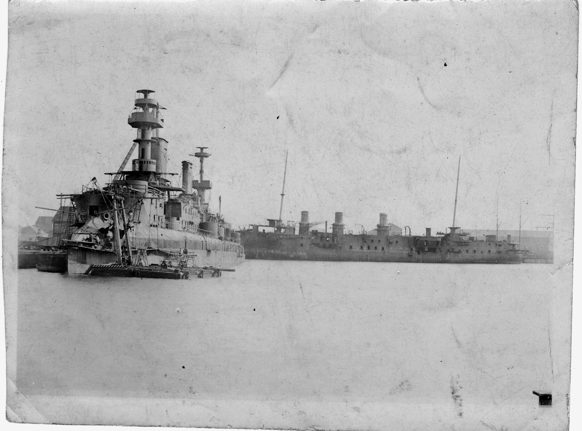
Catalogue number 51024 Masséna fitting out The warship shown here at the fitting out bay looks like the French battleship Masséna - note the pronounced bow ram and tumblehome, short military masts and one large and one narrow funnel. However, Masséna was built by the Chantier de la Loire in Nantes although the legend to the photograph states that it was taken in Dieppe. Even more confusing is the three-funnel Friant class cruiser under construction in the background, two were built in Cherbourg and one in Brest. Verso: "**** in the Dieppe port in September 1896" in French and in fine black ink script. 10.8cm x 7.8cm Gelatin silver print |
 |
|||||||||||||||||||||||||||||||||||||||||||||||||||||||||||||||||||||||||||||||||||||||||||
|
Catalogue number 135093 Dupleix This stern view of the French cruiser Dupleix shows the centre frames riveted along the centre line at the level of the outer bottom plating as far as the keel where the plates appear to be temporarily held in place by bolts. Verso: "First rivet going in on the cruiser Dupleix" in French. 17.3cm x 12.4cm Gelatin silver print |
|
|||||||||||||||||||||||||||||||||||||||||||||||||||||||||||||||||||||||||||||||||||||||||
|
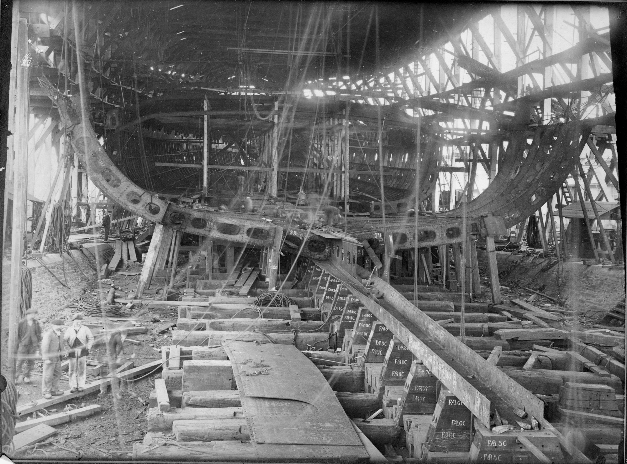
Catalogue number 136022 Republique, 1902 Again a stern view but of the French battleship République on the stocks in 1902. We can see the keel plate with the fastidious numbering of the middle line blocks. Many of the curved side frames are in place and the main deck beams are being set up. Note the slightly sloping protective deck. Verso: "Republique 31st January 1902" in French and in fine black ink script. 23.7cm x 17.7cm Gelatin silver print |
 |
|||||||||||||||||||||||||||||||||||||||||||||||||||||||||||||||||||||||||||||||||||||||
|
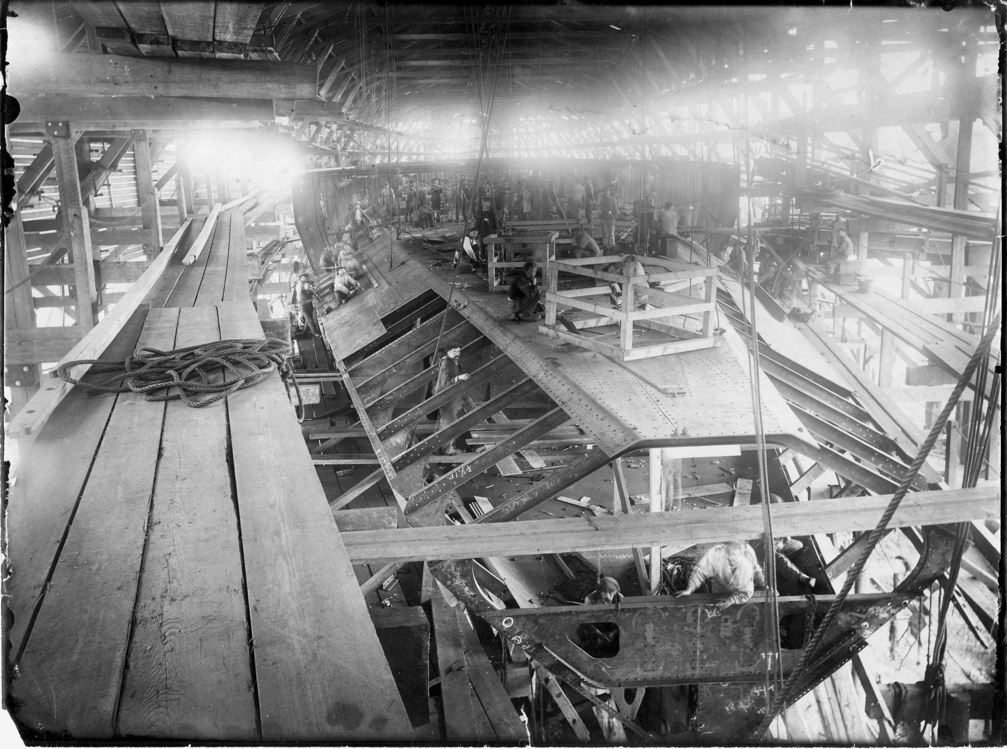
Catalogue number 136021 Leon Gambetta 1901 We can see the sloped protective deck towards the bow and the main deck, bolts holding plates in place ready for riveting. To the left of the photograph, a group of workmen are reaming the holes in a raised part of the sloping protective deck. Verso: "Léon Gambetta 28 June 1901" in French and in fine black ink script. 23.6cm x 17.8cm Gelatin silver print |
 |
|||||||||||||||||||||||||||||||||||||||||||||||||||||||||||||||||||||||||||||||||||||
|
Catalogue number 101179 Démocratie Brest The incomplete battleship Démocratie is being moved in the Arsenal in Brest, the gun turrets are not yet in place and fittings on the forecastle deck are being finished. Recto: "1900-1905 Patrie Suffren Republique Justice Verite Démocratie Liberte (lost). 1900-1905 Démocratie in the navy yard Brest)" in French and in light pencil. Verso: "The battleship Démocratie fitting out in the navy yard, Brest" in French and in light pencil. 10.3cm x 7.9cm Gelatin silver print |
 |
|||||||||||||||||||||||||||||||||||||||||||||||||||||||||||||||||||||||||||||||||||
|
Catalogue number 45228 Démocratie Brest, stern view, at the fitting out bay, Brest The turrets are now in place but the guns are yet to be mounted, the funnels and the military masts have been built-up. Verso: "Battleship "Démocratie" Our new battleships. The new battleship "Démocratie" fitting out in the port of Brest. "Démocratie". Sent by Mr Juillet, place des Jacobins at Morlaix (Finisterre) in French and in fine black ink script and light pencil. 17.1cm x 12.8cm Gelatin silver print |
 |
|||||||||||||||||||||||||||||||||||||||||||||||||||||||||||||||||||||||||||||||||
|
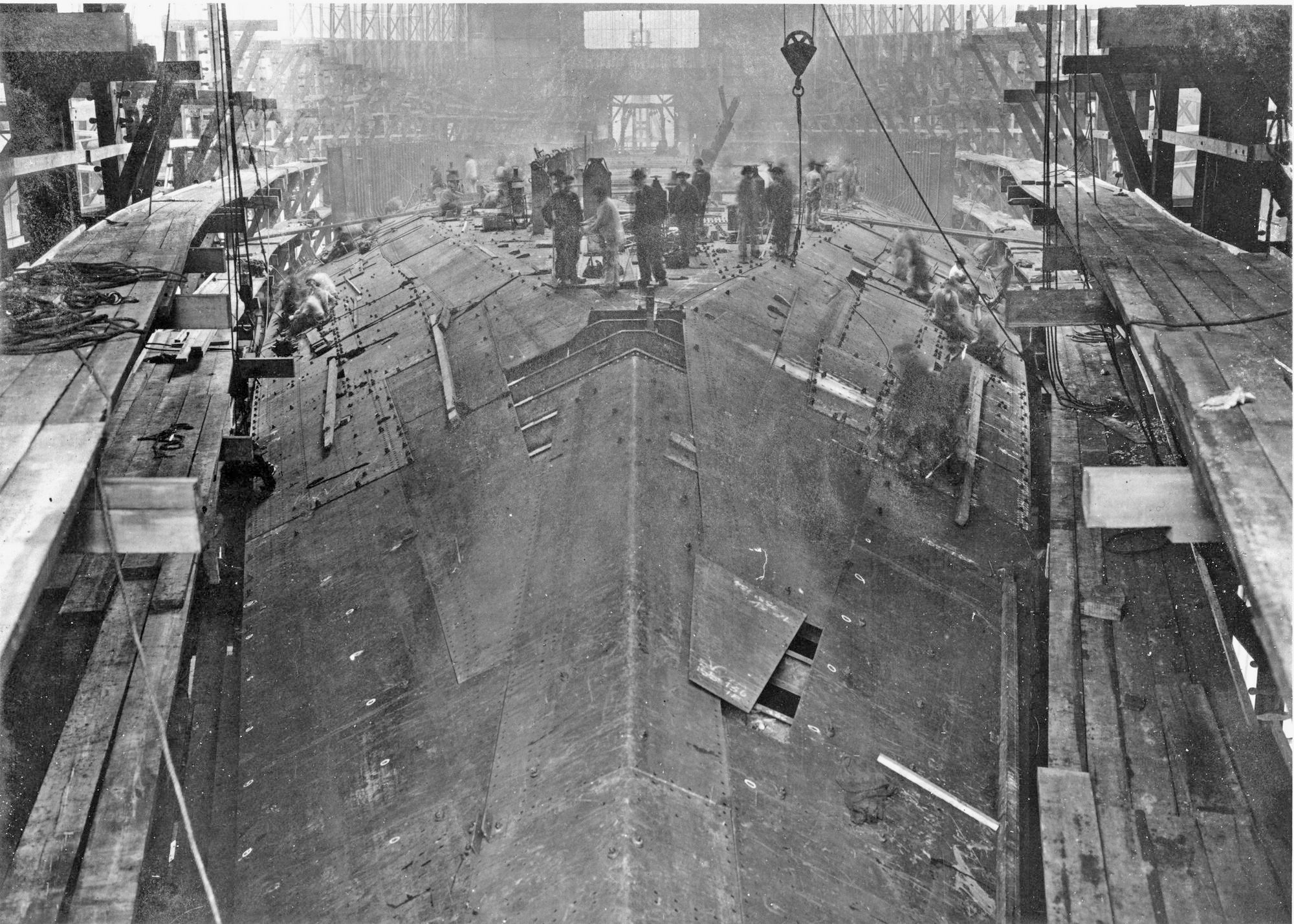
Catalogue number 111081 Bretagne, construction from 1912 A bow-on view of the French battleship Bretagtne under construction at Brest. The main deck plates and sloping protective deck plates are in place, being temporarily held by bolts prior to riveting. Further aft, the side frames of the upper deck can be seen. Verso: "27.2.1911 (sic) The first plates for the battleship Bretagne at the Point du Jour slip Brest" in French and in black ink. 22cm x 15.7cm Gelatin silver print |
 |
|||||||||||||||||||||||||||||||||||||||||||||||||||||||||||||||||||||||||||||||
|
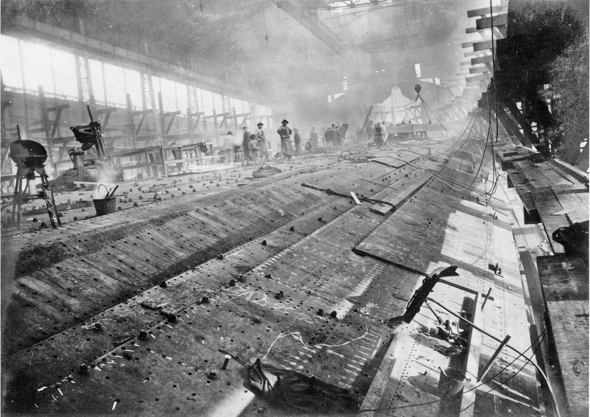
Catalogue number 111080 Bretagne, construction from 1912 A view forward showing, to the right of the photograph, some of the armoured plate of the protective slope held in place whilst another plate is being moved by crane. Verso: "March 1911 (sic) The first plates for the battleship Bretagne at the Point du Jour slip Brest" in French and in black ink. 22cm x 15.7cm Gelatin silver print |
 |
|||||||||||||||||||||||||||||||||||||||||||||||||||||||||||||||||||||||||||||
|
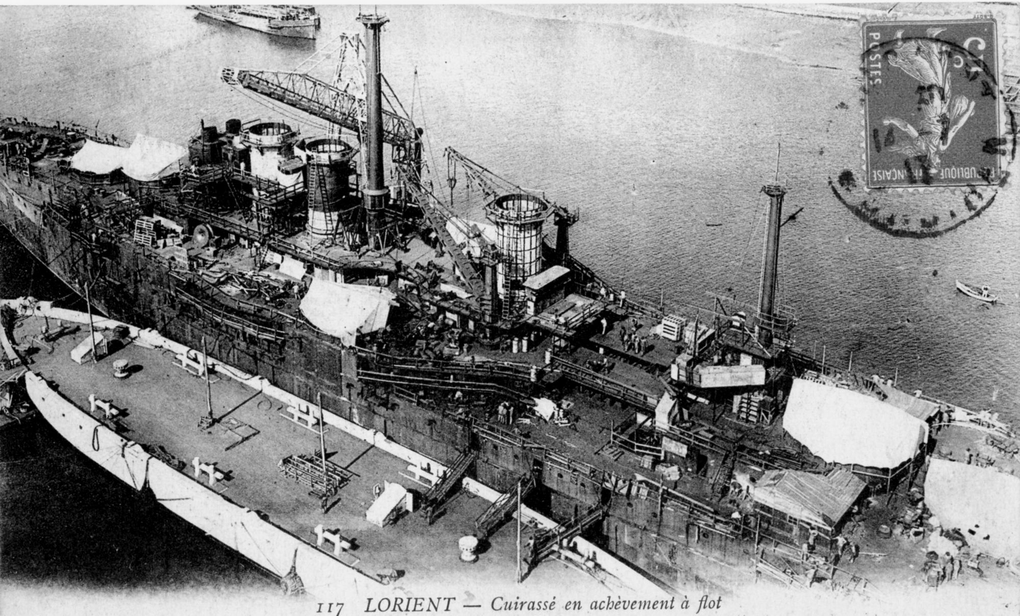
Catalogue number 123049 Courbet, fitting out at Lorient, 1913 The French battleship is well on the way to completion, the deck spaces for the turrets are covered with tarpaulins. Verso: Postcard posted in Lorient, 1917. 13.9cm x 8cm Printed image |
 |
|||||||||||||||||||||||||||||||||||||||||||||||||||||||||||||||||||||||||||
|
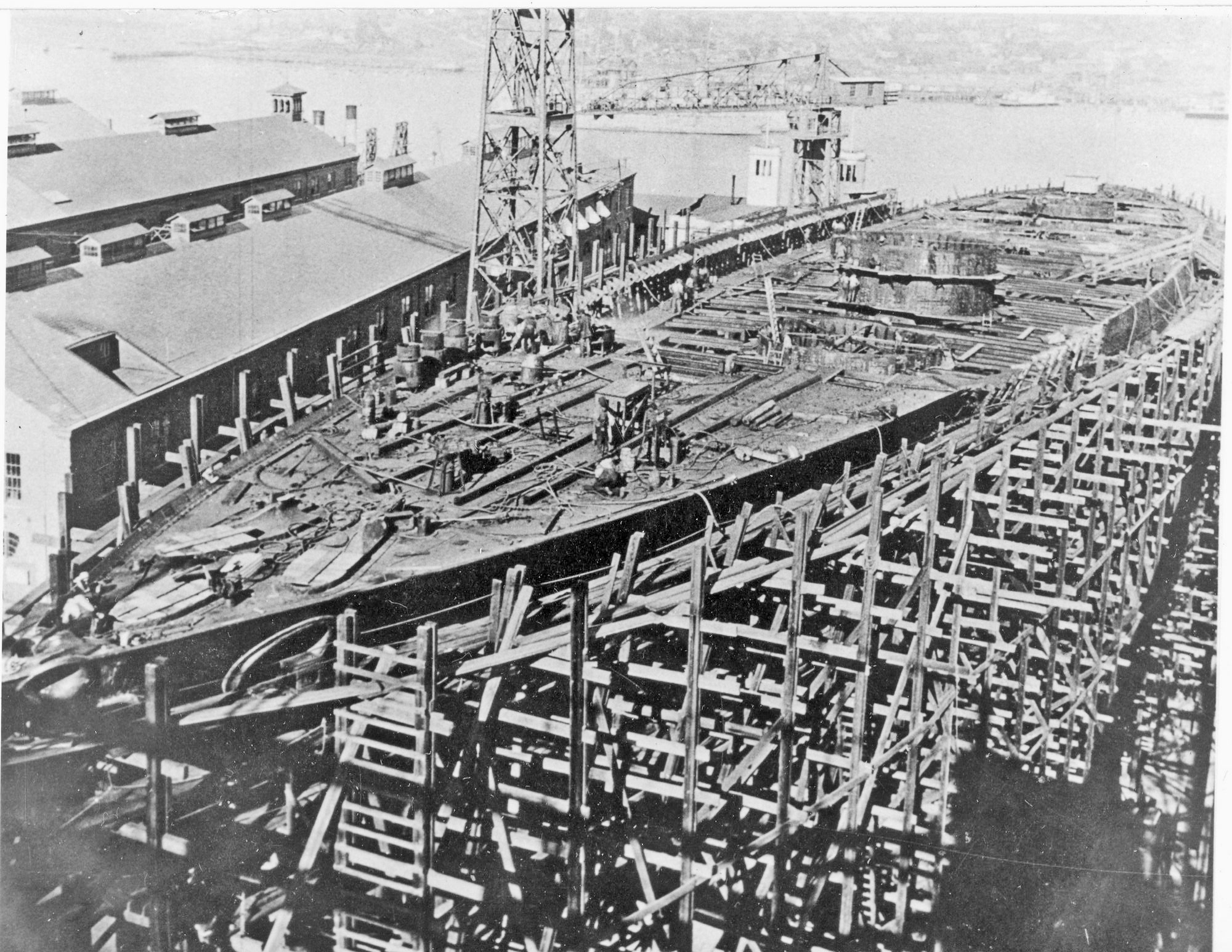
Catalogue number 133003 California BB44 1919 The first thing to notice is that we are at the Mare Island Navy Yard in California and the battleship can being constructed outside! The upper deck beams have the openings for the four gun turrets and the foredeck is being plated over. The plates seem to be held in place by bolts and we can see a number of cylindrical furnaces to be used when the plates are subsequently fixed by rivets. 11cm x 8.7cm Recent silver print |
 |
|||||||||||||||||||||||||||||||||||||||||||||||||||||||||||||||||||||||||
|
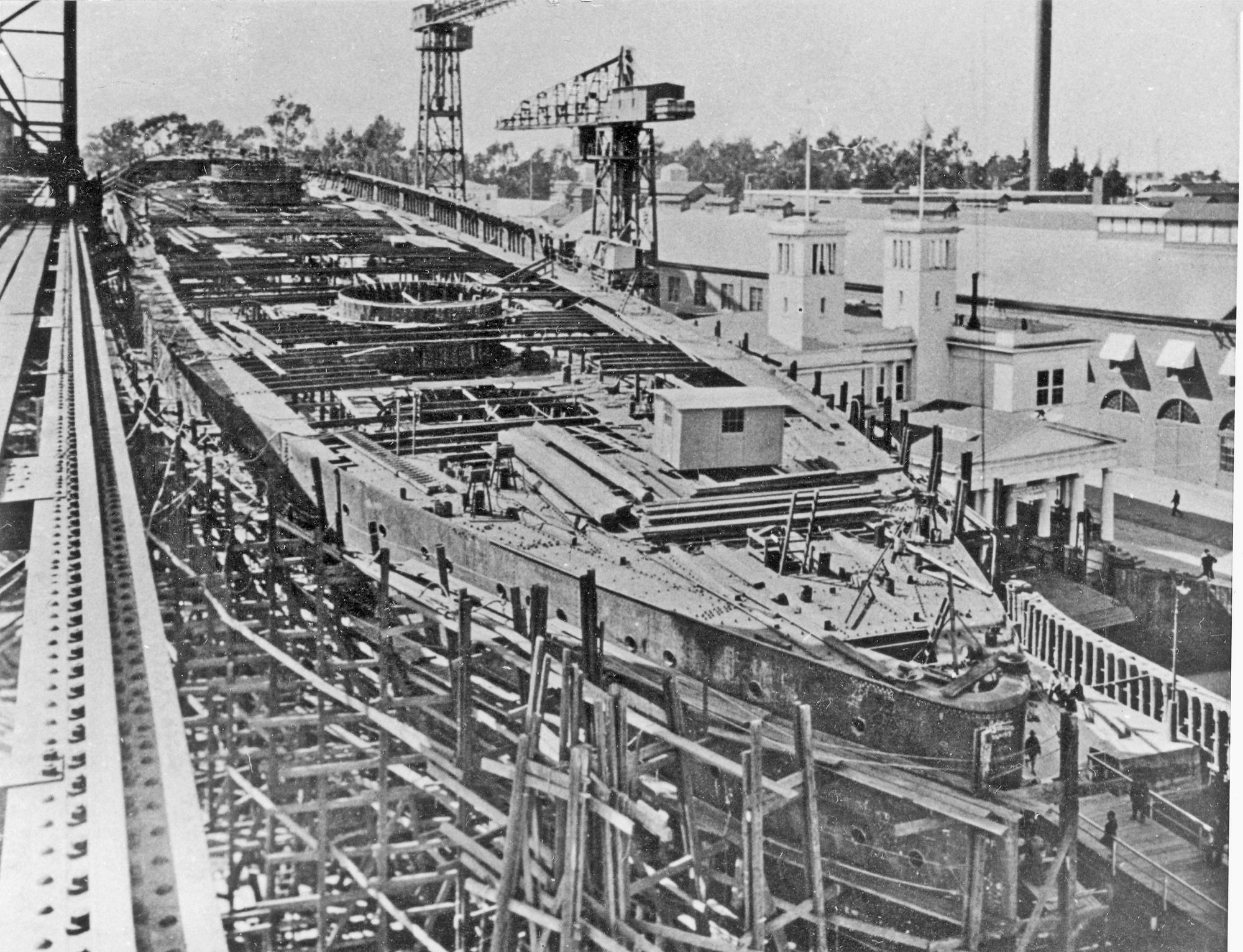
Catalogue number 133004 California BB44 1919 View from the stern of U.S.S. California, Ist October 1919. Much of the upper deck plating is yet to be riveted in place and the break in the forecastle deck can be clearly seen at the level of the righthand crane. The rails along which the lefthand crane runs are seen on the extreme left. Note the long wooden beams on deck by the shed. They are used to provisionally shore-up the deck beams during construction Verso: "California Oct 1, 1913" in light pencil. 11.1cm x 8.8cm Recent silver print |
 |
|||||||||||||||||||||||||||||||||||||||||||||||||||||||||||||||||||||||
|
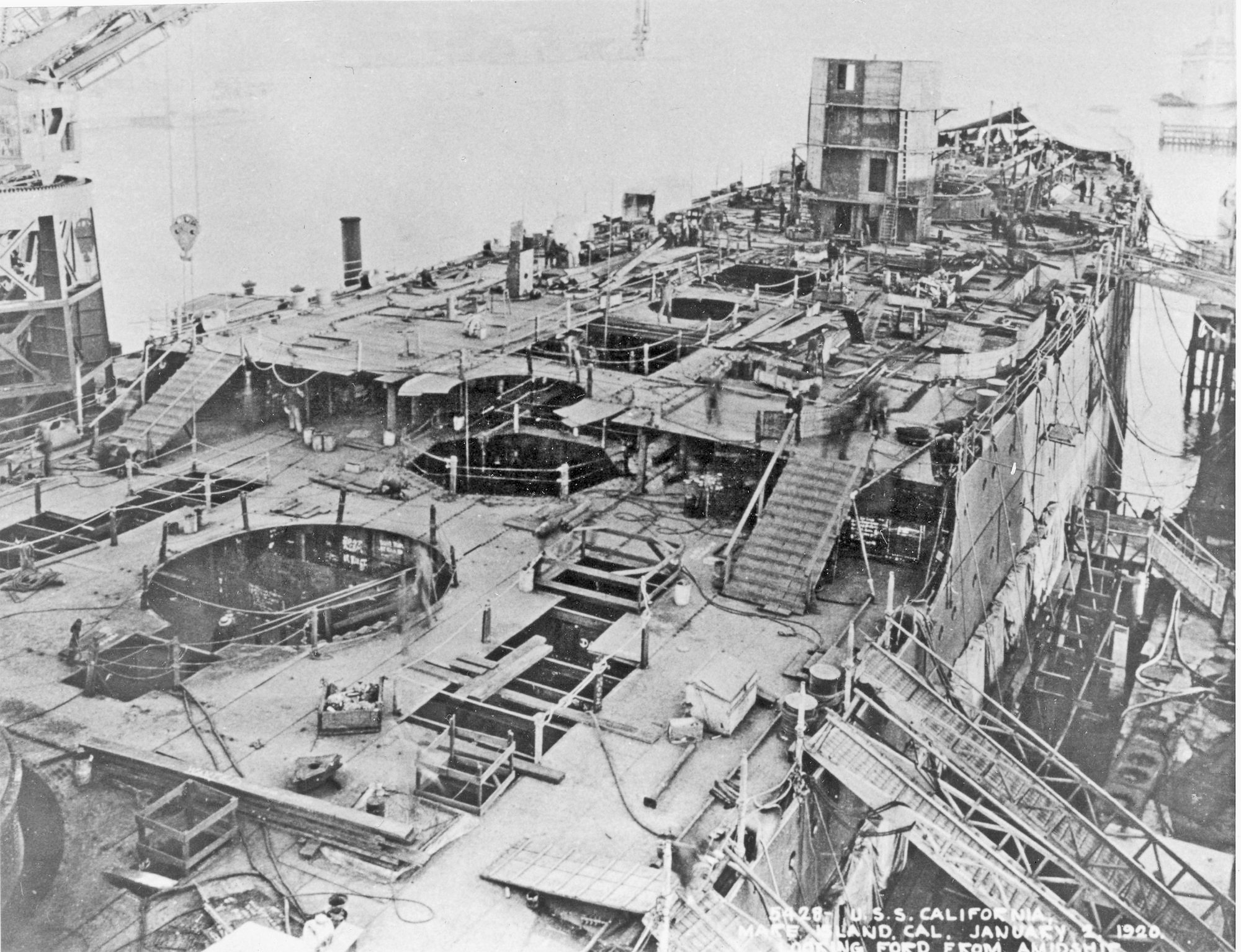
Catalogue number 133001 California 1920 An interesting view from midship looking forward to the forecasle deck, we can see the armoured conning tower (it had 16-inch armour) and the space for the funnels. Verso: "California Jan, 2,1920" in light pencil. 11.2cm x 8.7cm Recent silver print |
 |
|||||||||||||||||||||||||||||||||||||||||||||||||||||||||||||||||||||
|
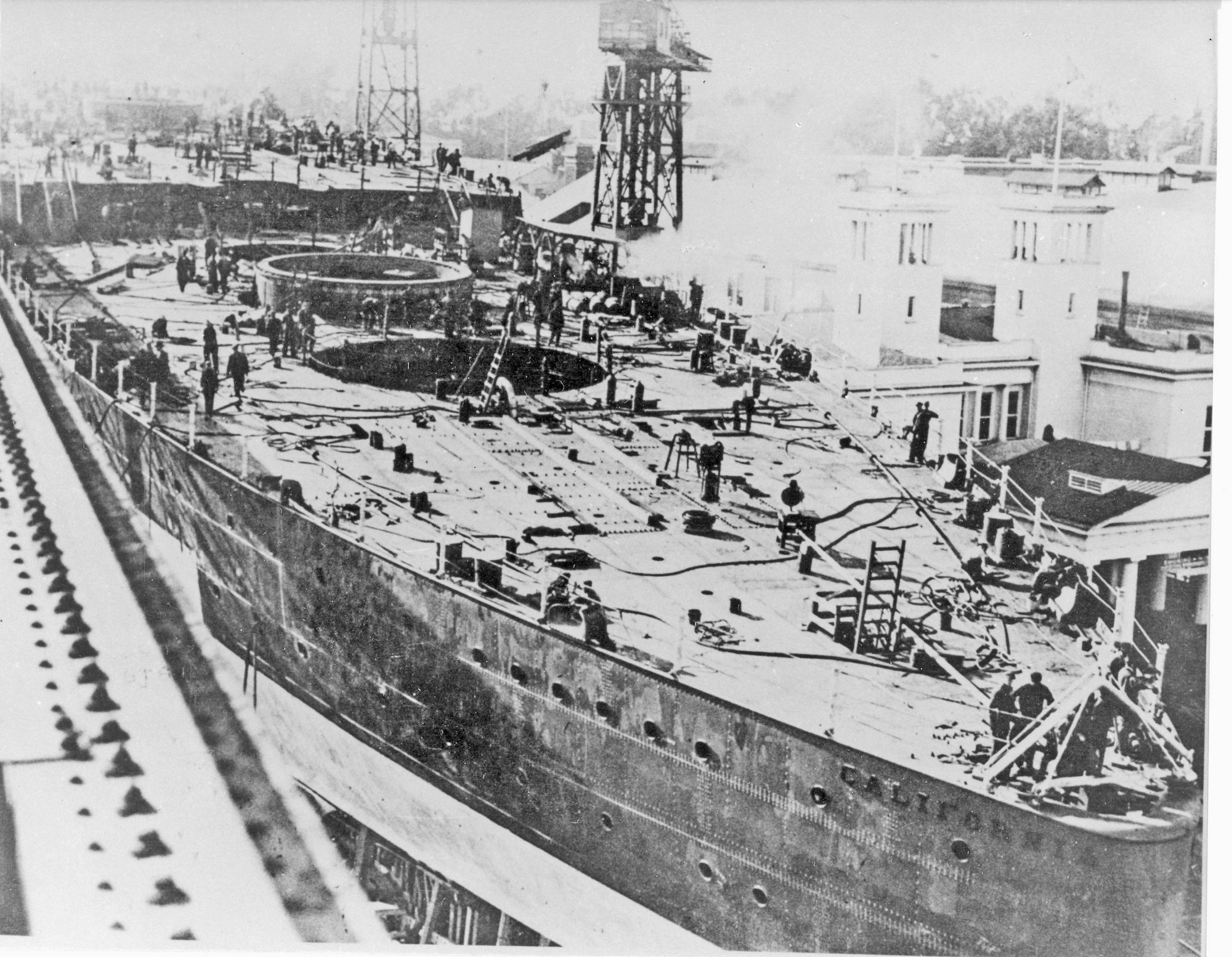
Catalogue number 133002 California 1920 View from the stern with one of the two aft gun turrets under construction, turret armour 18 inches. The close riveting of the hull plates can clearly be seen. 11cm x 8.8cm Recent silver print |
 |
|||||||||||||||||||||||||||||||||||||||||||||||||||||||||||||||||||
|
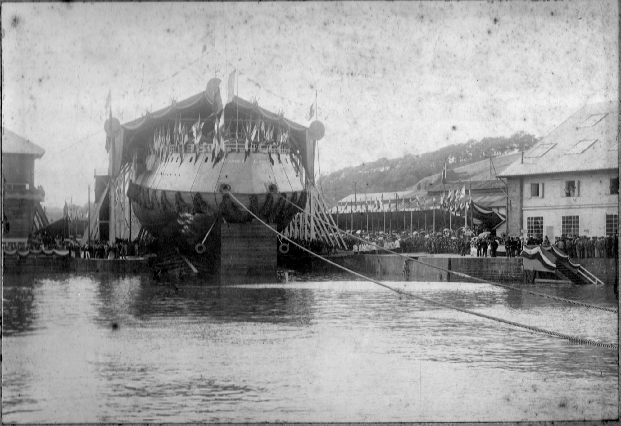
Catalogue number 90 F8 Launching of French battleship Suffren, 1899 Laid down in January 1899*, construction in the Brest Arsenal is said to have gone quickly and Suffren was launched in July of the same year. The two heavy hawsers are for tugs to pull the ship down the slip should there be a problem. (* Laid down date given as 1898 and launched as 1899 by Lecalve and Roche, Liste des bätiments de la flotte de guerre française. This date would seem more likely but 1899 is the date most often cited (eg Conway's All the World's Fighting ships 1860-1905). The Naval Annual, 1903 edited by Brassey does not help in deciding the date. Page 22 gives 1898 for the launch but in the listing of French warships, page 276, the date of launch is given as 1899!). We are not helped by the text on the verso of this photograph. Verso: "Launch of the battleship Suffren Brest 25 July 1898 (sic)" in French and in fine black ink script. 22.3cm x 15.4cm Gelatin silver print |
 |
|||||||||||||||||||||||||||||||||||||||||||||||||||||||||||||||||
|
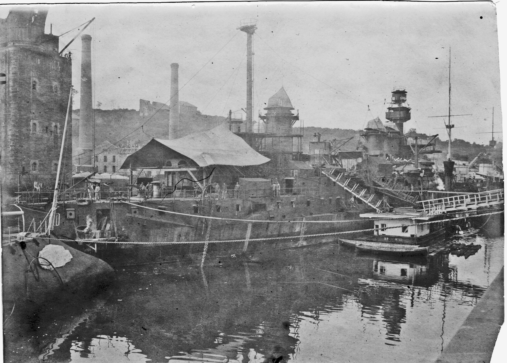
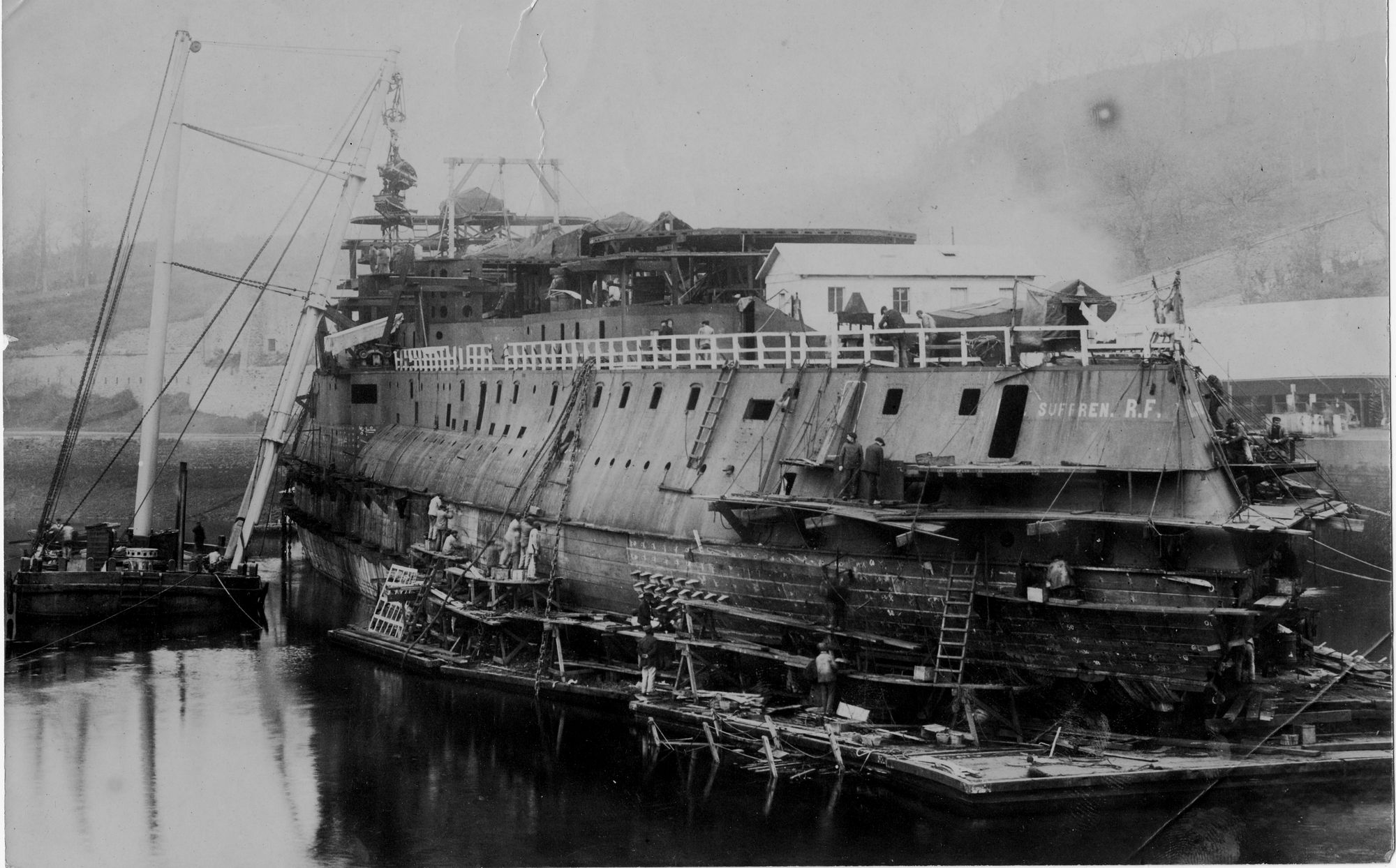
Catalogue number 38030 Fitting armour plate This magnificent photograph taken between 1899 and 1903 shows the French battleship Suffren in the fitting out dock. Many features of fitting out can be seen. Workers are preparing the holes in the teak backing on to which the armoured plate will be bolted. A floating shear legs is lowering what looks like engine room machinery parts into the hull. At the stern, workmen are fixing the sternwalk of the Captain's quarters. Verso: "Battleship "Suffren" under construction French Navy 16,500 horsepower 24 Niclausse boilers" in French and in pencil. 23cm x 16.2cm Albumin print |
 |
|||||||||||||||||||||||||||||||||||||||||||||||||||||||||||||||
|
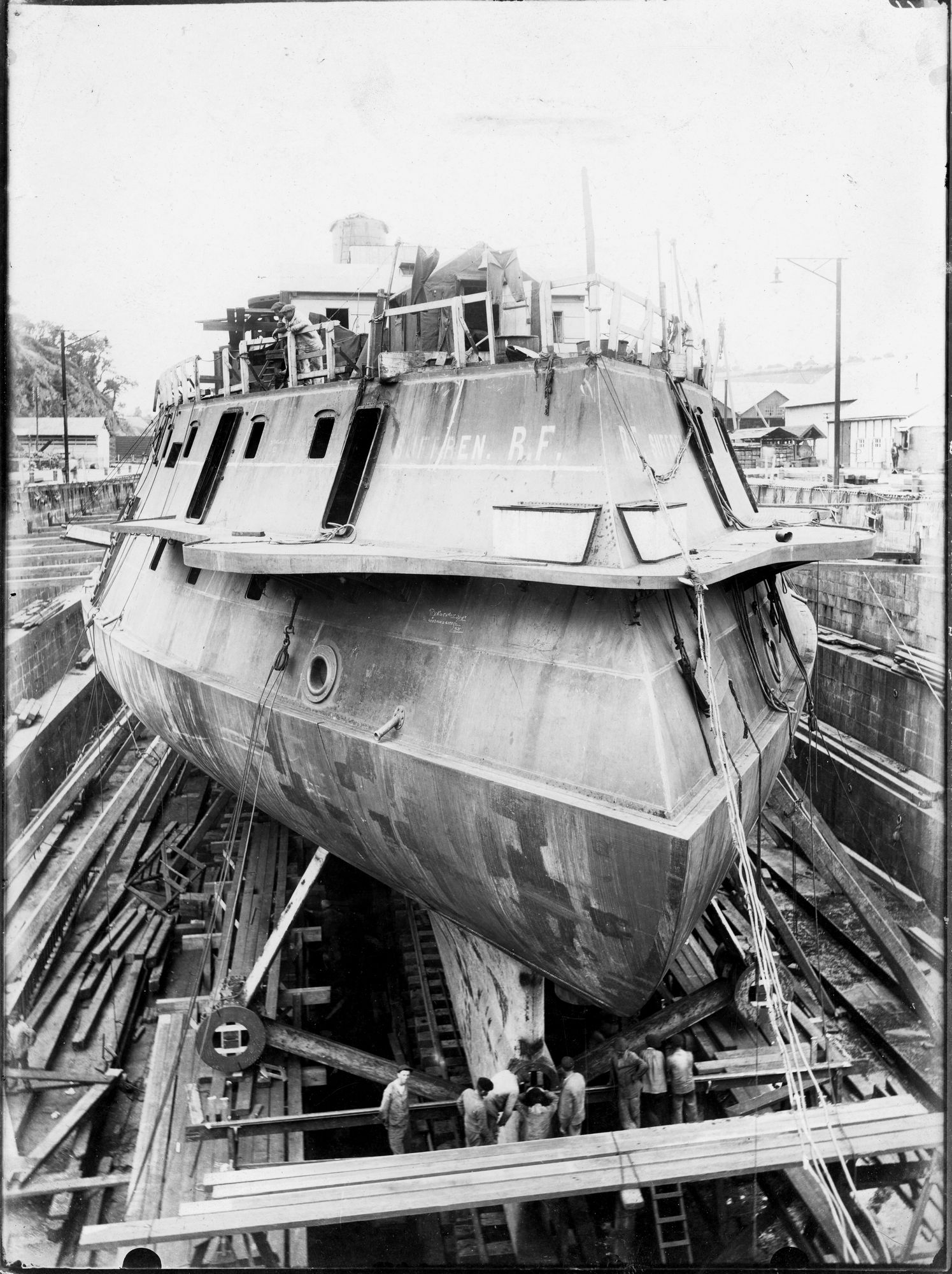
Catalogue number 136020 Suffren in dry dock We can see the thick armour belt from the stern, 12 inches amidships. Note the triple screw arrangement Verso: "Suffren 21st July 1900 stern view" in French and in fine black ink script. 18cm x 24cm Gelatin silver print |
 |
|||||||||||||||||||||||||||||||||||||||||||||||||||||||||||||
|
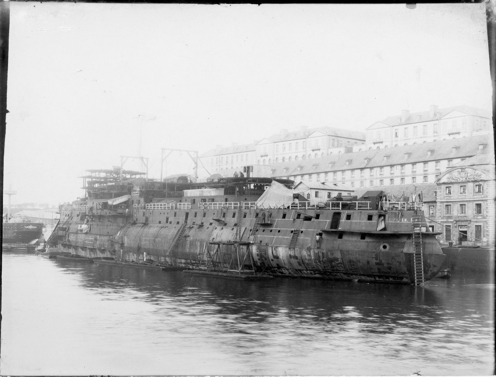
Catalogue number 136019 Fitting out on the dockside Suffren was the last of the classic French pre-dreadnoughts and fitting out took so long (completed 1903) that, with the launching of H.M.S. Dreadnought in 1906, she was obsolete from the outset. Armour has been fitted up to the level of the bridge and starboard 6.4-inch gun turret sponson. Verso: "Suffren stern view 22nd May 1900" in French and in fine black ink script. 18cm x 24.1cm Gelatin silver print |
 |
|||||||||||||||||||||||||||||||||||||||||||||||||||||||||||
|
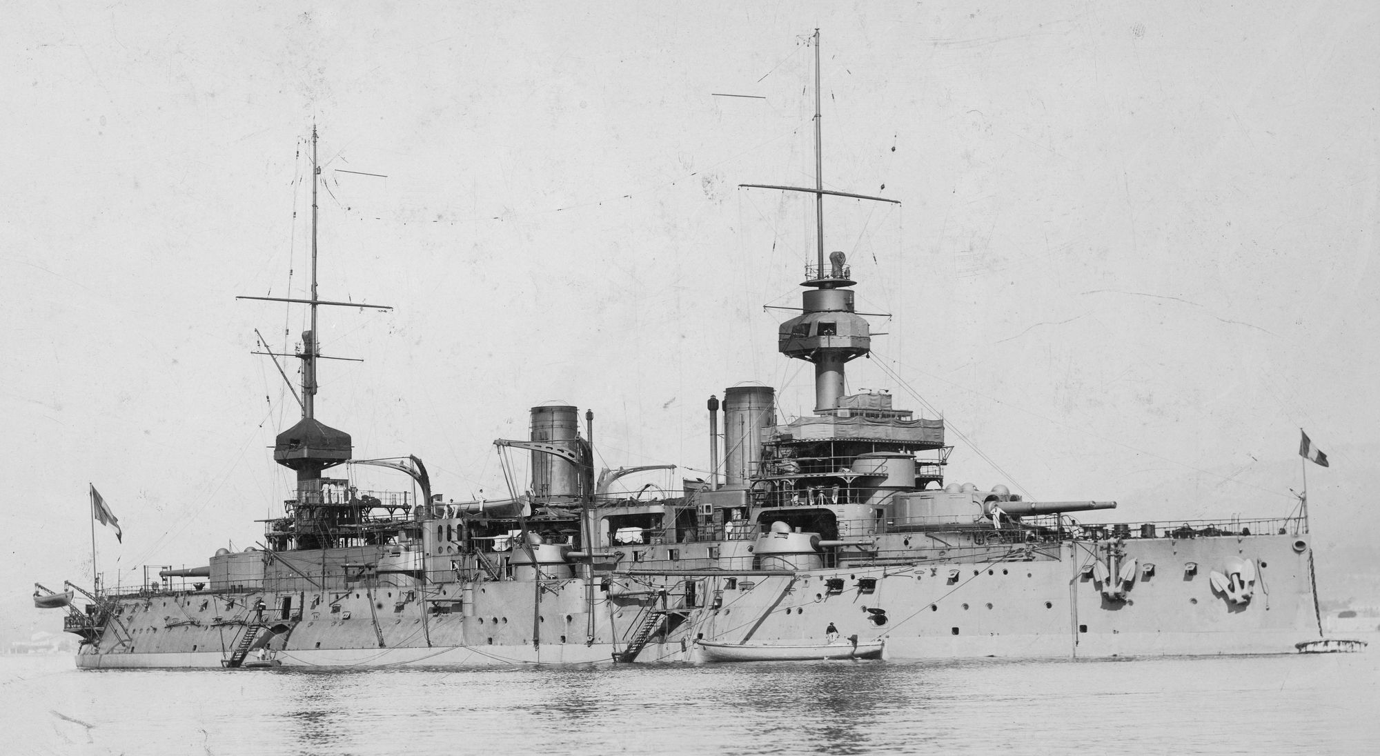
Catalogue number 89 F1 The commissioned battleship swinging off a buoy Completion of Suffren was delayed by the lack of fittings and the late delivery of the armour plate. Once commissioned, she was a solid-looking ship with strong lines and a tumblehome. Note the twin 305 mm/12-inch turrets fore and aft with a secondary armament of 164.7mm/6.5-inch guns (three in single turrets each side of the superstructure and two in sponsoned casemates either side over the tumblehome. We can see the armoured belt just above the waterline. 28.6cm x 22.5 cm Gelatin silver print |
 |
|||||||||||||||||||||||||||||||||||||||||||||||||||||||||
|
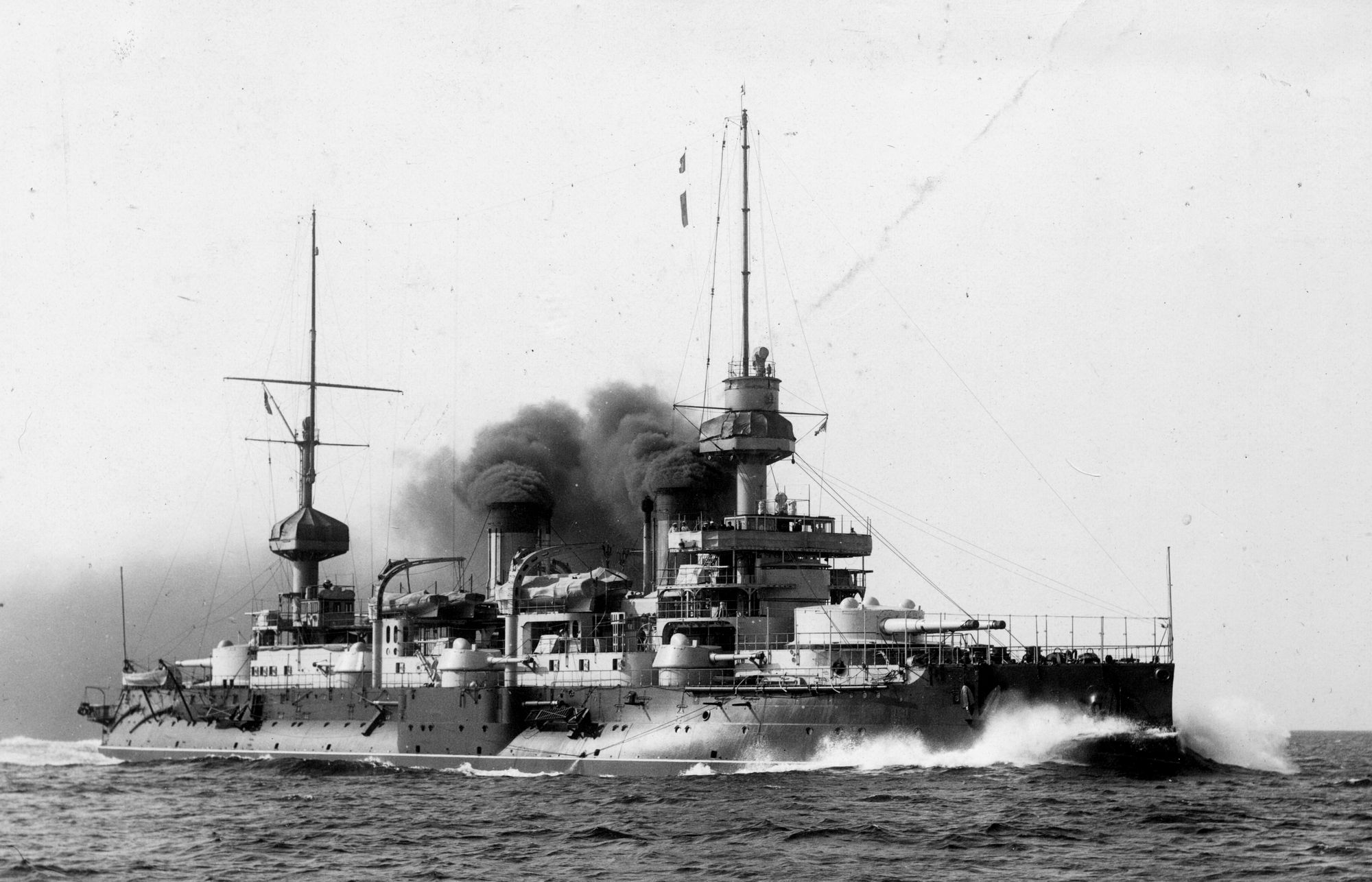
Catalogue number 30003 Speed trials Suffren reached slightly more than the design speed during trials hitting 17.9 kts. Fuel oil could be sprayed onto the burning coal to improve performance. Given the huge clouds of black smoke coming from the funnels, this may be the case in the photograph. Verso: ""Suffren" at 15kts, 17 September 1909" in French and in black ink 21.4cm x 15.4cm Gelatin silv09 |
 |
|||||||||||||||||||||||||||||||||||||||||||||||||||||||
|
Catalogue number 131082 Ark Royal main gear, Cammell Laird shipyard The aircraft carrier Ark Royal was laid down in 1935, launched in 1937 and was completed in 1938 at the Cammel Laird shipyard at Birkenhead, U.K. She had three shafts driven by geared steam turbines. Here we can see workmen hand-filing the teeth on the main gear wheel. To the left is the rotating blade assembly of one of the Parson marine turbines that went into Ark Royal. Behind the gear wheel, workmen are adjusting the turbine casting holding the fixed blades (see more below). Mid-left can be seen numerous roller bearings to be used for the different rotating axes. Verso:"D.28365 (13) Steam turbines (f) Dressing the main gear wheel for the aircraft carrier Ark Royal II." 20.1cm x 14.8cm Gelatin silver print |
 |
|||||||||||||||||||||||||||||||||||||||||||||||||||||
|
Catalogue number 131080 Cammell Laird shipyard, rotors for steam turbines Workmen fixing rotor blades to three steam turbines. Are these turbines for the Ark Royal? They seem to be small for an aircraft carrier. Whilst Ark Royal was being built, Cammell Laird had two destroyers for the Argentine Navy under construction, maybe these turbines are for them. Verso:"D. 28362. (10) Steam Turbine Engines (c) Work on steam turbine rotors. Each of these will later be installed in a turbine cylinder such as those shown in the next picture." 20.2cm x 14.9cm Gelatin silver print |
 |
|||||||||||||||||||||||||||||||||||||||||||||||||||
|
Catalogue number 131081 Fixed blades of the turbine cylinder, Cammell Laird shipyard Here we can see the half casing of the turbine cylinder showing the steam ducts. One man is fitting the fixed blades whilst another is working on the roller bearing of the rotor. Note the hammer and sickle chalked on the upper casing, top of photograph, just left of center. Verso:"D. 28363. (11) Steam Turbine Engines (d) Assembling the fixed blades of a turbine cylinder or case. The rota revolves in this, each wheel of rota blades fitting in between the wheels of the fixed blades in the cylinder. The rota blades are set at an angle causing the steam to come through at an angle. The fixed blades of the turbine case direct steam back to the next blades of the revolving rota." 18.6cm x cm x 14.7cm Gelatin silver print |
 |
|||||||||||||||||||||||||||||||||||||||||||||||||
|
Catalogue number 131079 Reduction gear box, Cammell Laird shipyard In this photograph, we can see two main gear wheels (top, far right and bottom, just right of center). The men seem to be working on the reduction gear box. Part of a second reduction gear box is shown far left, the letters "HP" by the bearing refer to the high pressure turbine Verso:"D. 28357. (5) A large British marine engine works. Here the various parts from the foundry and blacksmith's shop are machined and assembled. All the many items, making up marine engines are finally assembled in the engine pit, just as the ship's frames and plates go out to the building berth for erection." 14.8cm x 16.8cm Gelatin silver print |
 |
|||||||||||||||||||||||||||||||||||||||||||||||
|
Catalogue number 131078 Main engine bad, Cammell Laird shipyard The auxilary engines are marine diesels. Verso:"A section of the main engine bed is here going into place in the engine room. To the right are the auxilary engines. These engines play an important part in a ship's life. They supply light and power to work the water pumps, the winches and derricks for loading and unloading and the windlass for getting in the anchor. Electricity is needed to work the ship's ventilation system and for refrigeration. Communication between wheel house and engine room is electrically controlled." 14.8cm x 20.4cm Gelation silver print |
 |
|||||||||||||||||||||||||||||||||||||||||||||
|
Catalogue number 104034 French ship Duchaffault 1867 This Bourayne class cruiser, alternatively classed as an aviso, was laid down at Cherbourg in 1867 and was launched in 1872. It was armed with six cannons and became a coal hulk in 1896. The ship was wooden hulled and we can see the closely spaced frames that made these ships so solid. Verso : "Duchaffault 1868 Cherbourg" in pencil 25cm x 19cm Sepia print |
 |
|||||||||||||||||||||||||||||||||||||||||||
|
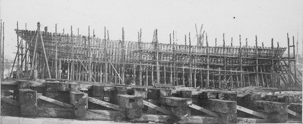
Catalogue number 104037 French aviso Seudre 1868 Seudre was a wooden-hulled screw transport aviso built for the French Navy in Rochefort between 1868 and 1872 to become a floating pontoon in 1891. The closely-spaced frames can clearly be seen and some elements of planking are in place. Verso:"7th April Seudre" and "Seudre Rochefort 1868" in pencil (translated from French) 23.7cm x 11.4cm Sepia print |
 |
|||||||||||||||||||||||||||||||||||||||||
|
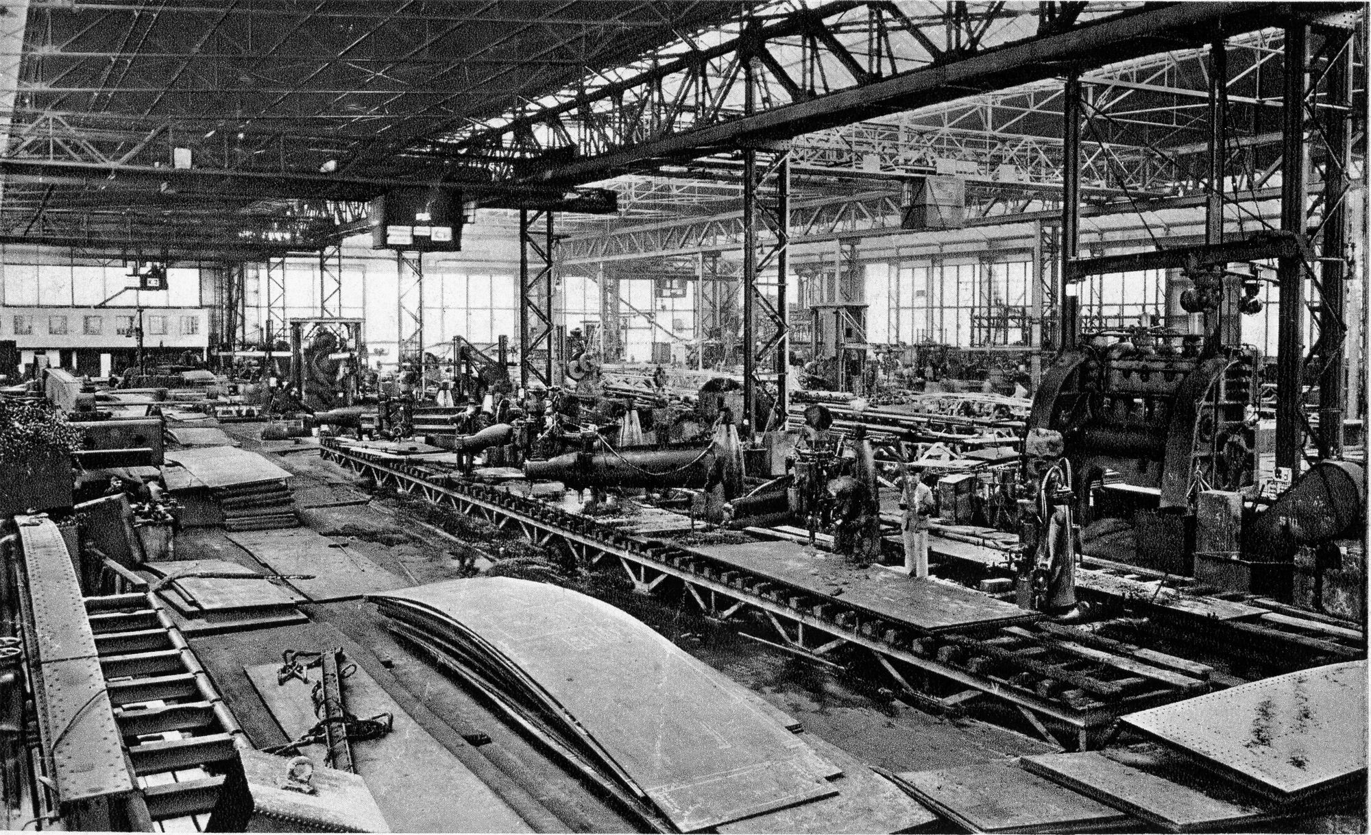
Catalogue number 97109 Deutsche Werke shipyard Kiel This image shows the Deutsche Werke shipyard at Kiel in 1939. Cut plates are arranged all over the shop floor, some of which have already been formed. In the centre of the image are drilling machines preparing the holes which will take the rivets. During construction, the plates will be riveted onto the frames. Recto: "Shipbuilding hall" (translated from German, "Schiffbauhalle") 17cm x 10.3 cm Printed image |
 |
|||||||||||||||||||||||||||||||||||||||
|
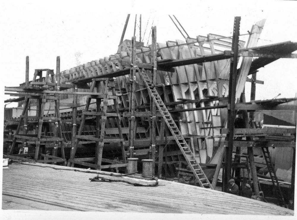
Catalogue number 24045 British destroyer World War 2 This is a photograph of the built-up frames of a British destroyer. The hull had to be strong to resist the hammering that a destroyer would get in service so the frames are close together and reinforced, destroyers were expected to ram an enemy ship if they had the chance. Some plates have been fitted to the side of the ship. 8cm x 5.4cm Gelatin silver print |
 |
|||||||||||||||||||||||||||||||||||||
|
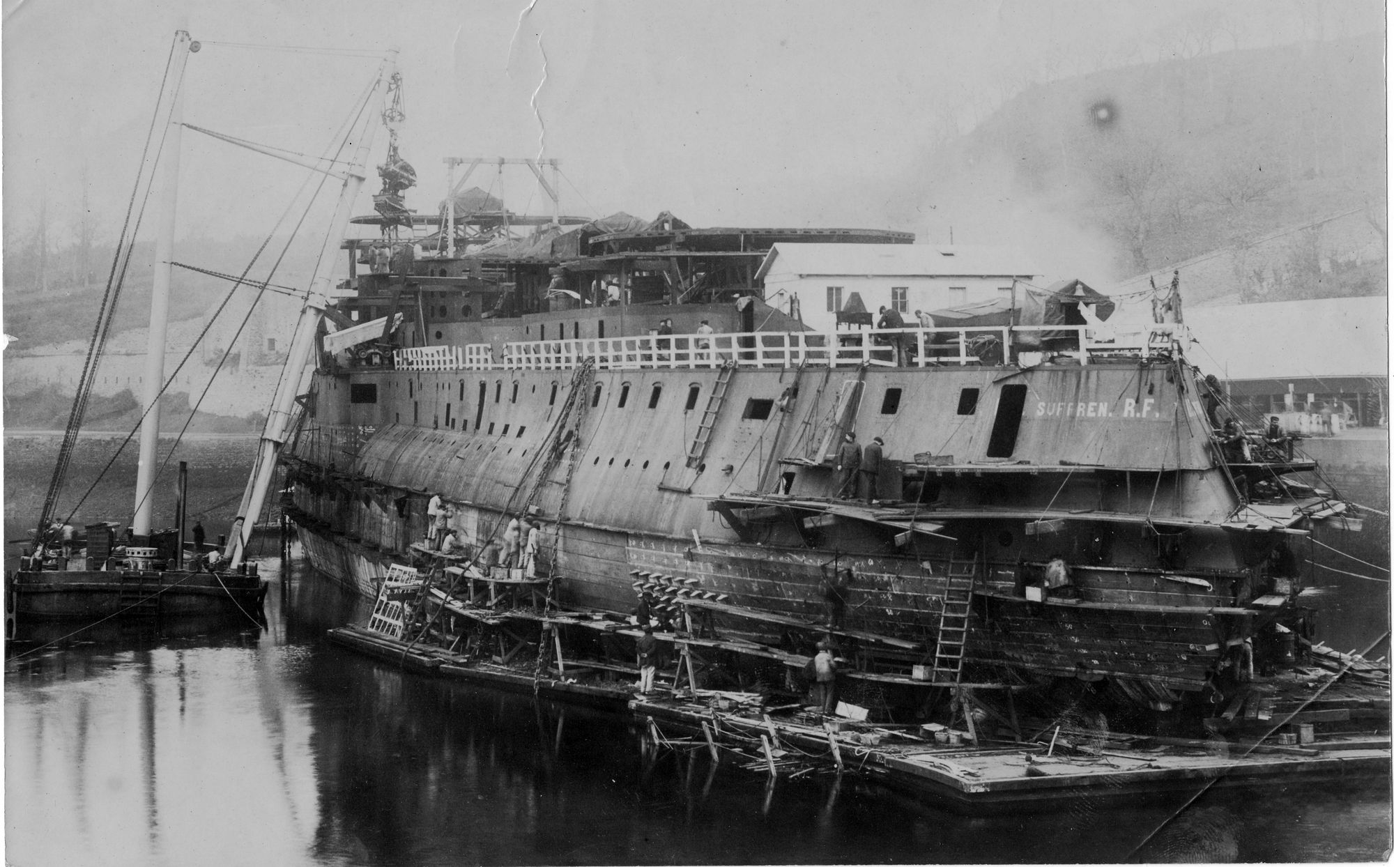
Catalogue number 38030 French battleship Suffren This magnificent photograph taken between 1899 and 1903 shows the French battleship Suffren in the fitting out dock. Many features of fitting out can be seen. Workers are preparing the holes in the teak backing on to which the armoured plate will be bolted. A floating shear legs is lowering what looks like engine room machinery parts into the hull. At the stern, workmen are fixing the sternwalk of the Captain's quarters. Verso: Battleship "Suffren" under construction French Navy 16,500 horsepower 24 Niclausse boilers (translated from French) in pencil. 23cm x 16.2cm Albumin print |
 |
|||||||||||||||||||||||||||||||||||
|
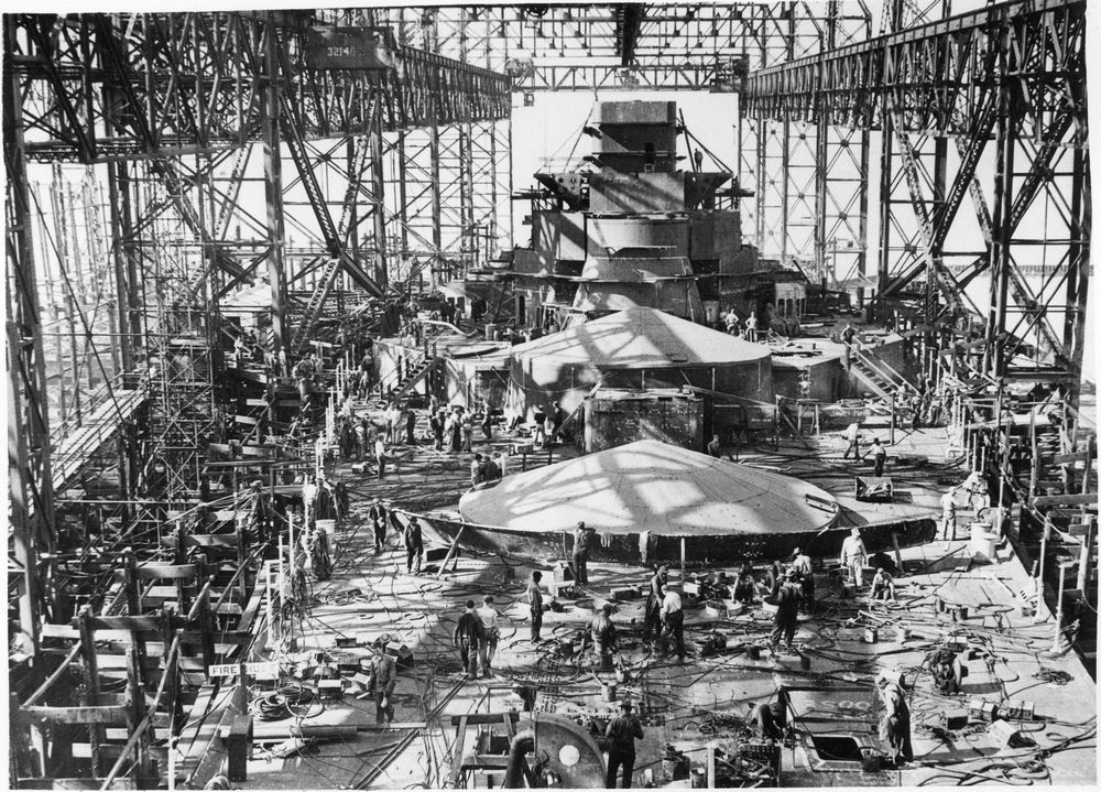
Catalogue number 101194 USS Indiana battleship The USS Indiana is in an advanced state here and workmen are all over the place. In the centre of the photograph, the forward breakwater is ready to be fixed to the foredeck. The two forward turret emplacements are covered over. The ship is still in the slipway and was launched in 1941. Verso: "Work proceeds feverishly on the United States Navy's new 35,000-ton battleship, Indiana, at the Newport News Shipbuilding and Drydock Company, Newport News, VA. The Indiana has since been launched, a valuable contribution to the United States Navy". 19.3cm x 13.9cm Gelatin silver print |
 |
|||||||||||||||||||||||||||||||||
|
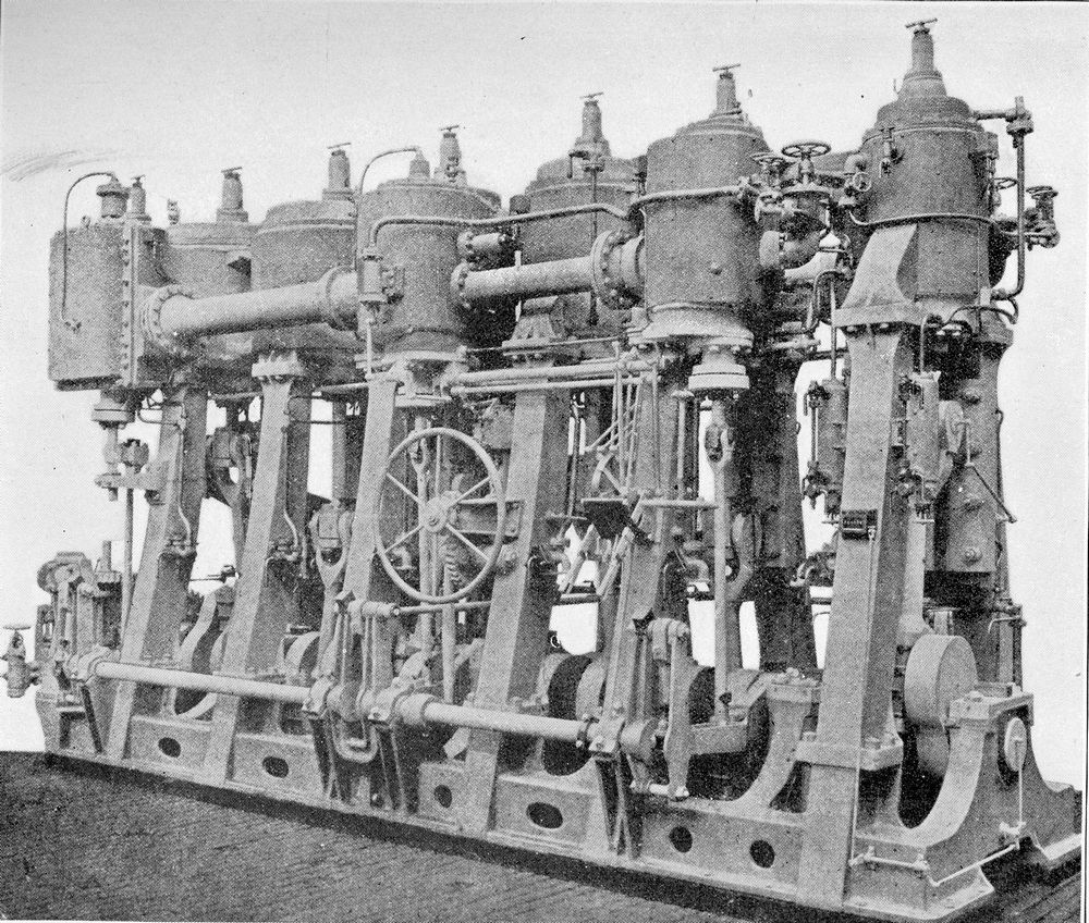
Catalogue number 102069 Triple expansion steam engine. 1900 HMS Duncan had two sets of four cylinder inverted triple expansion steam engines. At 18 000 hp, the Duncan class battleships were the first to steam at 19knots with steam provided by 24 Belleville boilers working at a pressure of 300lbs. These engines were huge, there were two cylinders of 33 ½ inch diameter, two of 54 ½inches and four low pressure cylinders of 63 inch diameter. The stroke of each piston was 4 feet long and the engine turned at 120 revolutions per minute. The repetitive back-and-forth movement of each piston acting on the crankshaft converts the reciprocating motion into a circular motion. Imagine each piston shooting down the cylinder under pressure and at the end of its course, the movement is reversed and the mass of the piston shoots back up the cylinder to repeat the back and forth movement! A major problem with steam engines was that with each change in direction there was a great loss of kinetic energy and the construction of the engine had to be massive to be able to support all the mechanical forces. The engines were built by the Thames Iron Works Shipbuilding and Engineering Co. Ltd. Recto: "Engines of H.M.S. " Duncan " (1900) Model of the port set of screw engines of the four-cylinder triple expansion type for battleships. Working pressure of steam, 300lb.per sq. in.: 18,000 total I.H.P. at 120 revs. Per minute" 13.2cm x 7.3 cm Printed image |
 |
|||||||||||||||||||||||||||||||
|
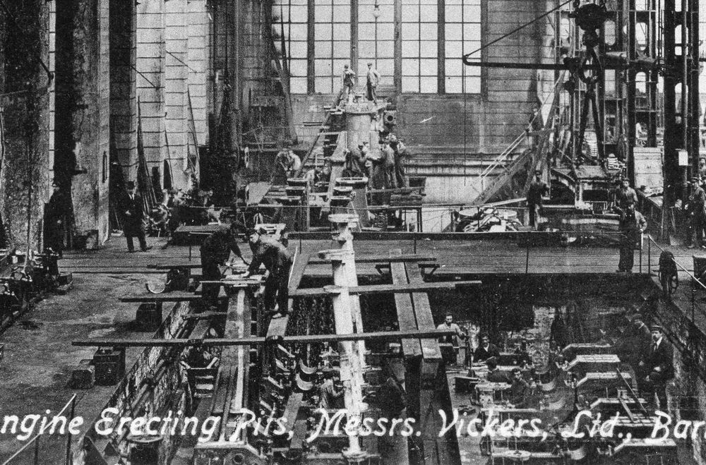
Catalogue number 105004 Building a marine steam engine. This is an enlargement of a photograph showing several marine steam engines at different stages of construction. In the foreground, right, we can see the bedplate and the crankshaft bearings of an engine. To the left foreground and behind are two incomplete engines with the cylinder supports being set into place. In the far background is an engine in a more advanced state of construction with the cylinders in place. Some idea of the date of the photograph can be guessed from presence of the man wearing a top hat to the left of the gangway - the beginning of the 20th century? Recto: "Marine Engine Erecting Pits, Messrs. Vickers, Ltd., Barrow-in-Furness" 13.7cm x 8.8cm Gelatin silver print |
 |
|||||||||||||||||||||||||||||
|
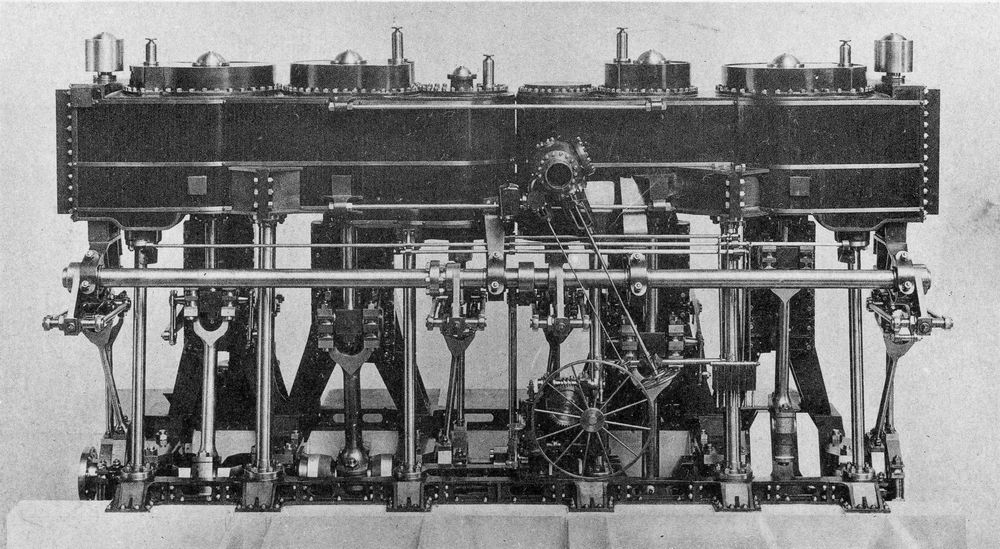
Catalogue number From Notes on Naval Progress 1900 Marine steam engine, 1898 The Armstrong company at Elswick, UK built this triple expansion engine for the Chilean Navy training ship General Baquedano launched in 1898. There are two sets of cylinders, from right to left, we can see the twin high pressure cylinders then the medium and finally the twin low pressure cylinders. By a novel system of disconnecting and securing the bottom ends of the connecting and valve rods of one set of three cylinders, it was possible to drive the propeller with only one half of the engine for economy cruising. The engine drove a feathering propeller and the ship was rigged as a sailing bark. Steam was supplied by four Belleville boilers at 300lb pressure. 13.3cm x 11.4cm Printed image |
 |
|||||||||||||||||||||||||||
|
Catalogue number 49003 General Baquedano Chilean Navy training ship General Baquedano, launched 5th July 1898 and commissioned on 22nd August 1899, stopped serving as a training ship in 1935. Verso: "Chilien Gal. Baquedano No 34" in pencil. 17.9cm x 12.8cm Gelatin silver print |
 |
|||||||||||||||||||||||||
|
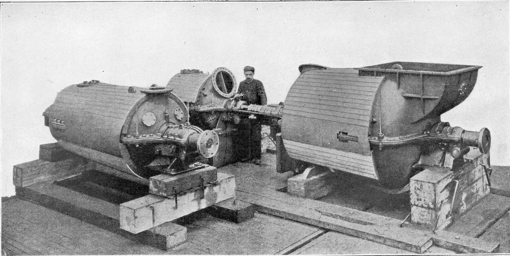
Catalogue number From Notes on Naval Progress 1900 HMS Viper In the late 1880's, the Royal Navy became aware of the increasing menace posed by the fast and light torpedo boats being developed abroad and particularly in France. It was a problem to produce powerful and rapid ships capable of catching enemy torpedo boats. The triple expansion engine had perhaps reached its limits to power a large, heavily armed torpedo boat destroyer that could overtake an enemy torpedo boat, especially in a rough sea. The first attempts to produce such a vessel were a failure. Two developments were to radically change the situation - the steam turbine and water tube boilers. The Honorable Charles Parsons, a young engineer, developed the steam turbine, an engine that turned on an axis, power being developed by high pressure steam directed on to blades fixed to the rotor. Here we see one set of turbines that were fitted in the destroyer HMS Viper, the 35-inch high pressure turbine is in the foreground and the 50-inch low pressure turbine and the small reversing turbine are in the background. Steam was provided by four Yarrow straight-tube boilers at 250lb/sq.in. to propel Viper along at an incredible 34.8 knots and without any of the vibrations associated with reciprocal steam engines. 19cm x 9.5cm Printed image |
 |
|||||||||||||||||||||||
|
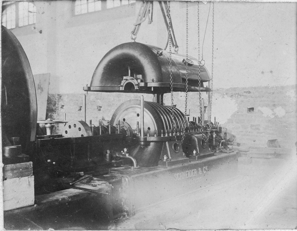
Catalogue number 101178 Schneider steam turbine With the upper casing removed in this Schneider Le Creusot steam turbine, we can see the blades of the multiple-rotor, multiple-stage turbine. Steam enters the turbine at one end and as the steam passes over each stage of the blading, it expands as it transfers its energy to the rotor so each stage of blading is larger to capture as much energy as possible. The used steam is then run to a condenser. The drive shaft of the turbine can be seen on the left-hand side of the rotor. Verso: "Schneider le Creusot." 10.8cm x 8.3cm Gelatin silver print |
 |
|||||||||||||||||||||
|
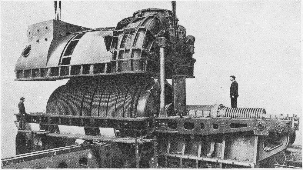
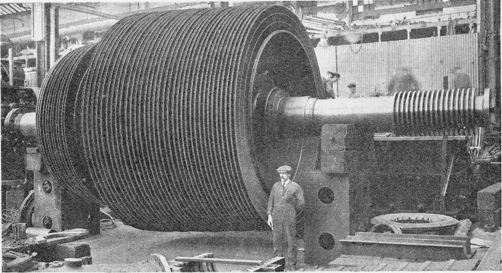
Catalogue number 105059 & 105060 Marine turbines from John Brown &Co. Ltd. The John Brown company of Clydebank took an early interest in marine steam turbines and became the most successful builder of battleship and cruiser engines. They engined warships for the Royal Navy as well as other Navies. The two images show turbines for a battleship. The men standing by the turbine give some idea of its size. 105059: 12.9cm x 7.2cm Printed image, 105060: 12.5cm x 7cm Printed image |
 |
 |
|||||||||||||||||
|
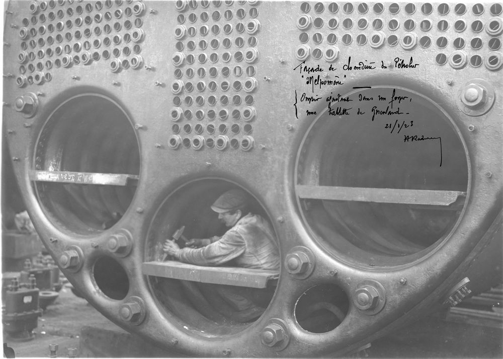
Catalogue number 99084 Steam production, a Scotch boiler A Scotch boiler was made up of a large diameter but short length cylindrical boiler shell. Corrugated fire tubes run from the boiler front to a combustion chamber at the back. The hot gases then flow back through a bank of flue tubes to the smoke box fixed to the front of the boiler and above the furnace entrance. Water surrounded the combustion box and the flue tubes. A Scotch marine boiler contained much more water than a water-tube boiler and took a longer time to raise steam. Steaming up had to be slow to avoid leaks due to the unequal expansion of the stiff boiler shell and the thinner flue tubes. Here we can see three fire tubes, corrugated to withstand thermal expansion, and the flue tubes that will vent into the smoke box. Recto: "Façade de chaudiere du Petrolier "Melpomone" Ouvrier ajustant dans son foyer une tablette de Grienland (sic) - 21/1/23", "Front end of a boiler for the tanker "Melpomone" workman ajusting the Grienland (sic) fire grate - 21/1/23" in ink. 22.8cm x 16.1cm Gelatin silver print |
 |
||||||||||||||||
|
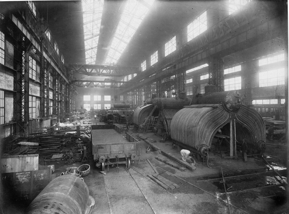
Catalogue number 99073 Water tube boilers, from a series of nine photographs taken between 1922 and 1924 at the Ateliers et Chantiers de la Gironde, Bordeaux, France. In a water-tube boiler, the water flows through the bank of tubes and the hot gases circulate around the tubes within the boiler shell. These boilers could raise steam quicker than the Scotch boiler, they could withstand heavy forcing and they were lighter in weight. However, the complex form of the tubes and the associated expansion under heating meant that they were prone to leaks at the joint with the water drums. The high steam pressures required by the more and more powerful expansion engines could be obtained. The French Normand boilers shown in this photograph are much like the British Thornycroft and Yarrow boilers that were fitted in Royal Navy vessels. The large upper water drum from which the steam is tapped can be seen at the apex of the inverted V of the water tubes. Additional water drums are at the base of the inverted V. Behind the first boiler we can see one of the downcomers that ensured circulation of water between the upper and lower drums. Verso: "16-6-24" 23.2cm x 17.4cm Gelatin silver print, |
 |
||||||||||||||
|
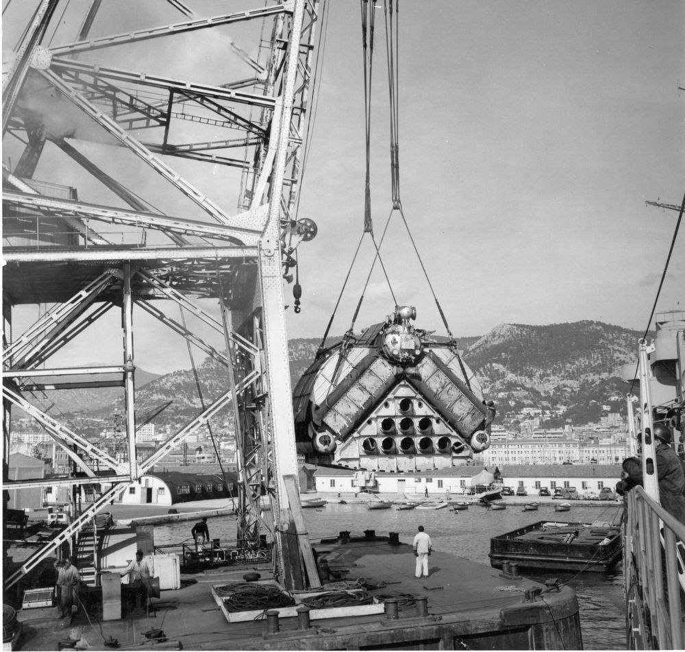
Catalogue number 102020 Normand boiler, Toulon Naval base. An idea of the size of this water-tube boiler can be had by comparing the height of the men on the floating crane. This is an oil-fired boiler, see the number of furnaces, being lifted by a floating crane at the Toulon Naval base. Judging by the old cars in the background - Citroen traction avant, 2CV, an Alfa Romeo Giuliette and two Peugeot 203 - this photograph was taken in the 1950s or early 1960s. 17.1cm x 16.9cm Gelatin silver print |
 |
||||||||||||
|
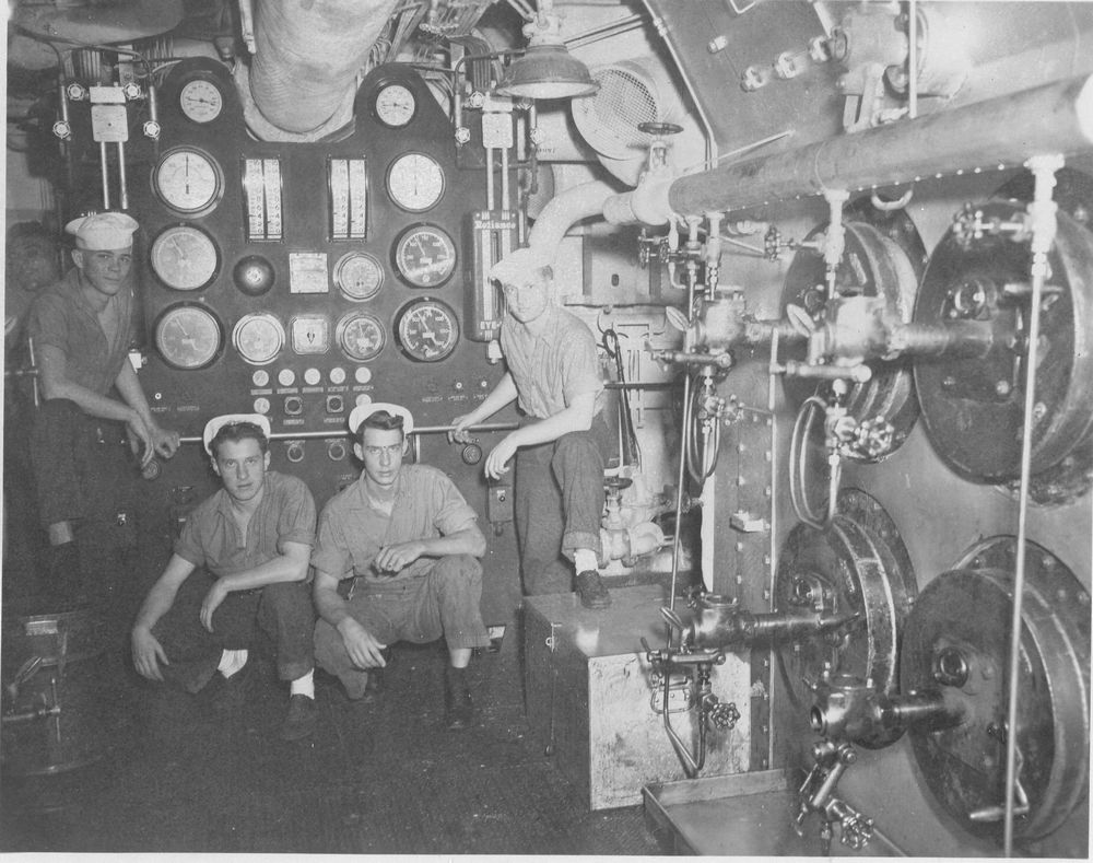
Catalogue number 105063 Oil-fired furnace This photograph was taken in the boiler room of an American warship and it shows four oil-fired furnaces. The fuel oil supply comes off the large pipe just above the furnaces and each burner has its own valve to regulate the flow of oil. There is a drip tray below the furnaces to catch any oil spills. The advantages of using oil instead of coal are numerous - no backbreaking work loading coal, simple replenishment in port and at sea, increased endurance and performance for the same weight of fuel, easier stowage and it requires fewer personnel in the boiler room. 11.8cm x 9.2cm Gelatin silver printi> |
 |
||||||||||
|
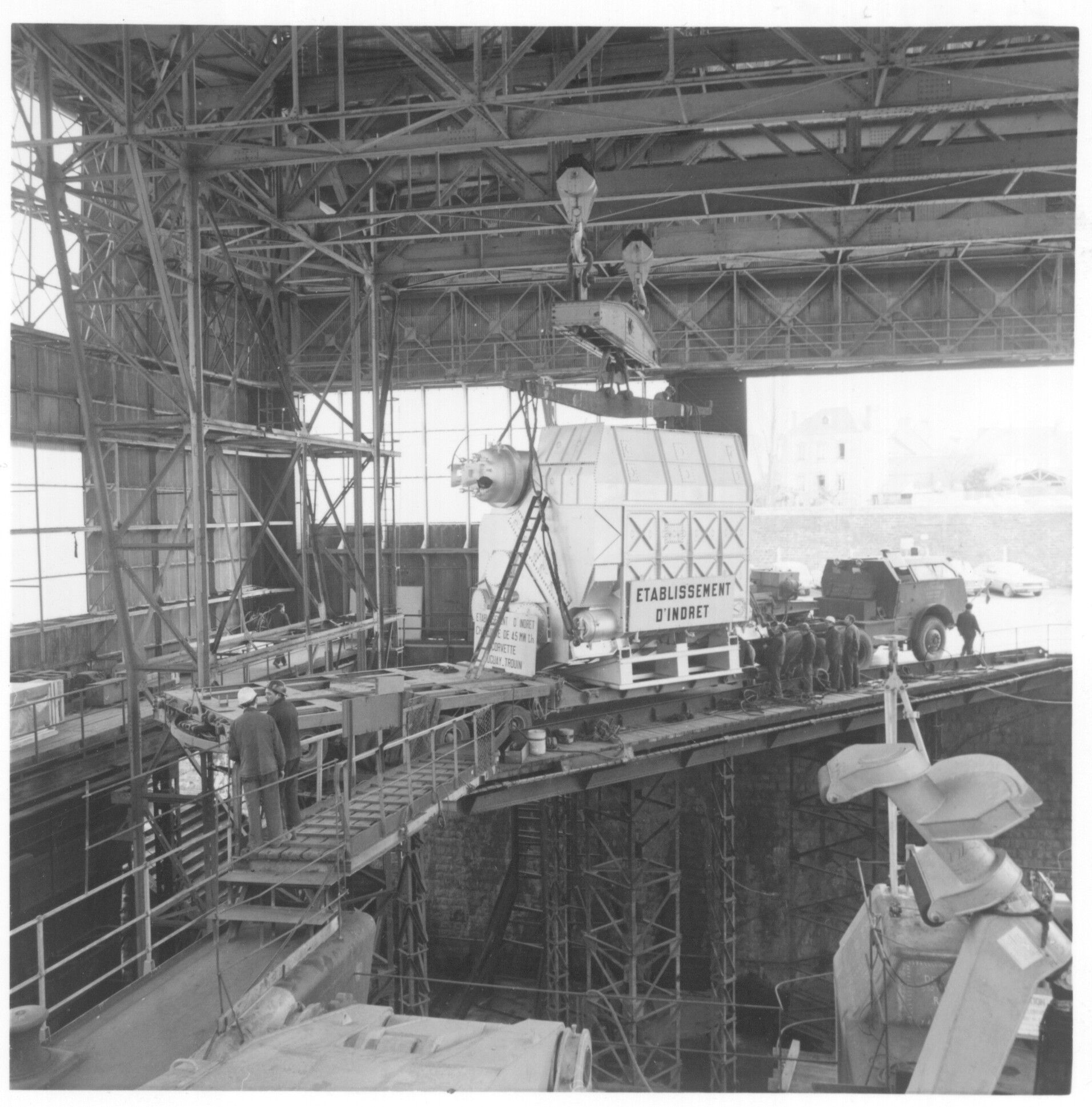
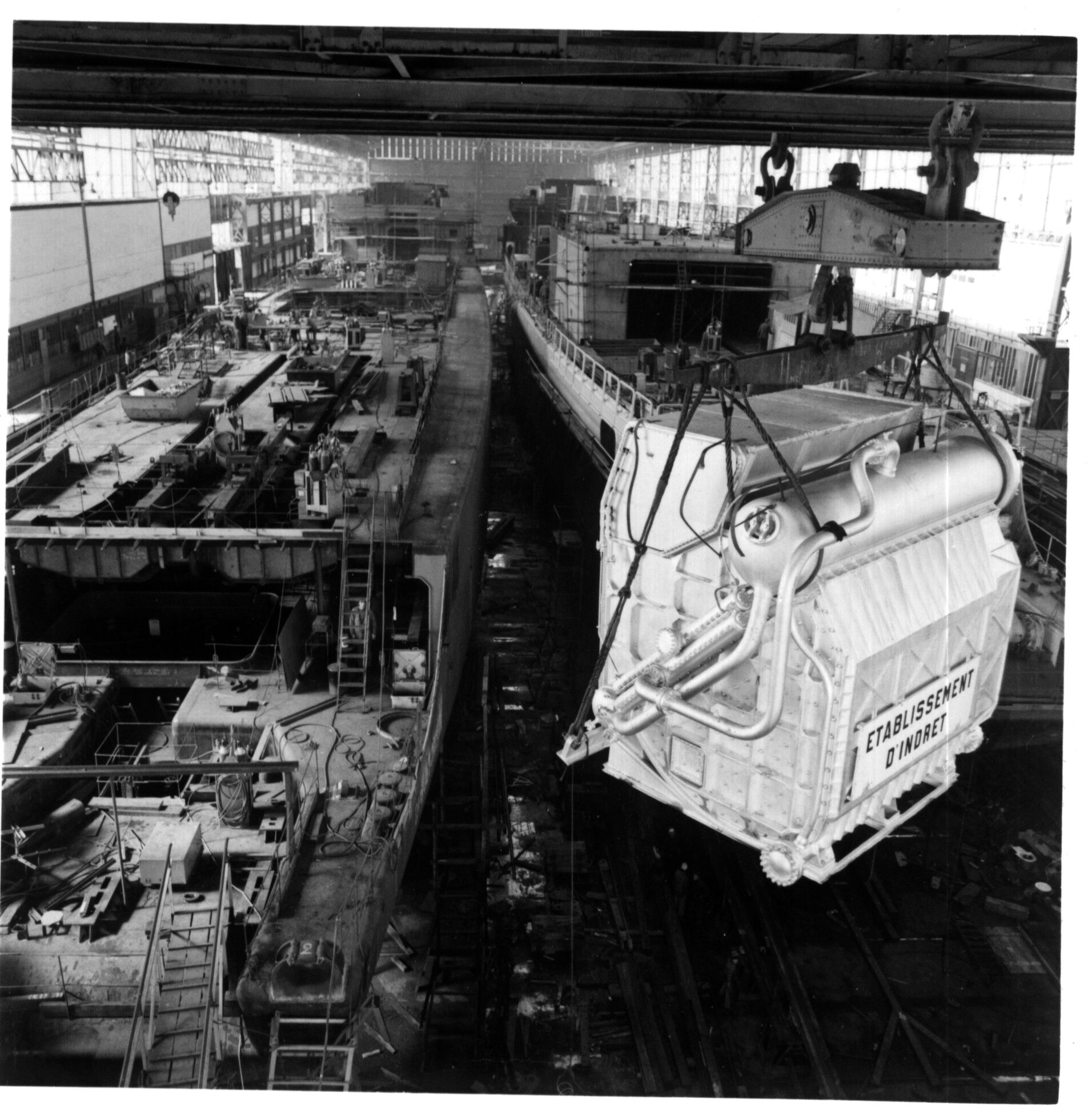
Catalogue number 71119 French Navy Frigate Tourville The French frigate Tourville was commissioned in 1975 and had four superheat, multi-tubular boilers, one of which is shown here at the Lorient Naval yard. The boilers provided steam for two groups of turbines. We can see the main water drum on the upper left part of the boiler. 7.9cm x 7.8cm Gelatin silver print |
 |
||||||||
|
Catalogue number 71113 French Navy Frigate Tourville From a series of 16 photographs concerning the construction and launching of Tourville 7.8cm x 7.9cm Gelatin silver print |
 |
||||||
|
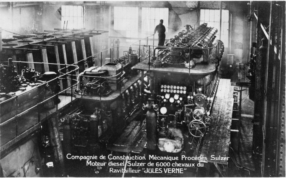
Catalogue number 105107 Early marine diesel engines The Jules Verne was a French Navy submarine tender laid down in 1929 and commissioned in 1932. The two Sulzer diesel engines each with its own shaft gave the ship a speed of 16kts at 110 rpm. Some idea of the size of each cylinder can be made by comparing the size of the man standing at the top of the motor. The Compagnie de Construction Mécanique Sulzer was founded in 1918 by the French government as a joint venture to build the marine diesel engines of the Swiss Sulzer company. The factory was alongside the Seine at Saint Denis. 13cm x 8cm Gelatin silver print |
 |
||||
|
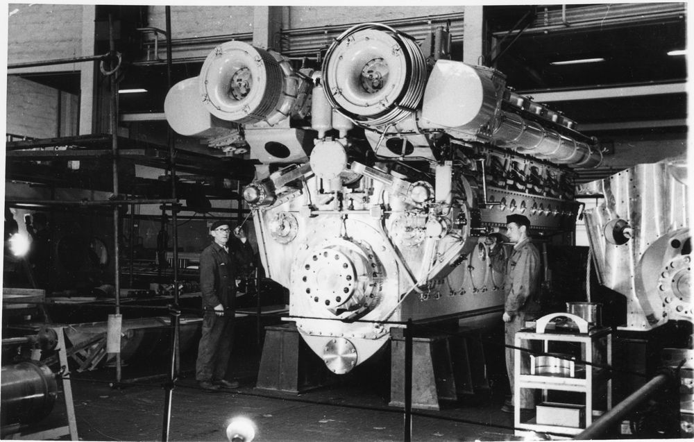
Catalogue number 99084 Marine diesel engine, French Navy Frigate Protet This V twelve cylinder diesel semi-rapid engine has a bore of 40cm and a stroke of 46cm. It ran at 520 rpm and weighed 7.2 metric tons. The two turbochargers can be seen either side of the cylinder head. This engine equipped the Commandant Rivière class dual purpose frigates of the French Navy, built in the late 50s and early 60s, and gave them a speed of 25kts. Compare the size and performance of this engine with that of the Jules Verne! Verso: "Erecting workshop 15th March 1952 (sic)( more likely 1962)- Motor SGCM/ACB - Sloop Protet 4 SEMT-Pielstick PC12 engines, 4,000 horsepower two shafts. S.G.C.M."(translated from French) 17.6cm x 11.2cm |
 |
||
|
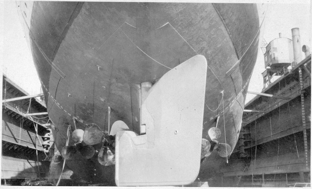
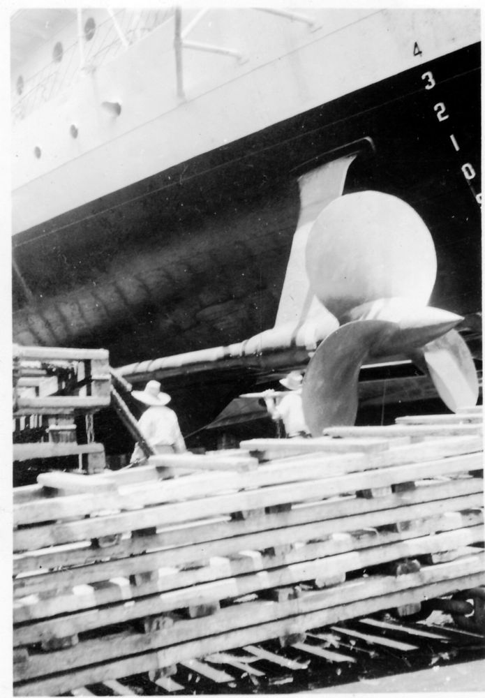
Catalogue number 35269 Propellers, HMS Ramillies, laid down 1913, completed 1917 The last element in the propulsion system of a warship is the propeller. This photograph shows HMS Ramillies (laid down 1913, completed 1917) in dry-dock with the keel and three of the four 3-blade screws showing. The outer screws were 9ft 3 in diameter, the inner screws 10ft, the propeller pitch (distance the propeller would theoretically move forward in one revolution) was outer screws 9ft 6in, inner screws 10ft. They turned at 300 rpm powered by Parsons turbines and Babock and Wilcox boilers for a design speed of 23 kts (full trials were never made, this class of ships going straight into war service, average speed for Ramillies is given as 20.5kts). The high pressure ahead and astern plus cruising turbines acted on the outer shafts, the low pressure ahead and astern turbines acted on the inner shafts. Verso: "screws & rudder. Ramillies" 13.4cm x 8cm Gelatin silver print |
 |
|
Catalogue number 66030 US destroyer propeller This photograph is of USS Stewart DD224 (laid down 1919, commissioned 1920) in dry-dock for overhaul at the Cavity Navy Yard, Philippines April 1940. Steam geared turbines acting on two shafts gave a speed of 35kts. We can see that the pitch of propeller is more pronounced than in Ramillies to take advantage of the greater power available from the geared turbines. Verso: "Prop of the Stewart. In Olongapo Navy yard P.I." 5.5cm x 8.1cm Gelatin silver print |
 |